| 
Configuration example for ATM DSL with PPPoE
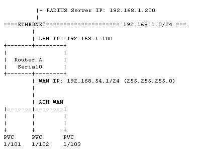
This sample configuration shows an ImageStream router connected to a Digital Subscriber Line aggregation circuit. Each PVC represents a DSL customer terminated on the router. Each PVC is connected to the router via an ATM circuit from a DSLAM.
Before You Start
Be sure to have three separate IP subnets, one for the WAN network and two for the Ethernets connected to the routers. Each WAN port connected to the point-to-point WAN must have it's own IP address from the same IP network. Since they are on the same IP network, they will have the same netmask.
These IP network addresses are given to you by your Internet Service Provider, your leased line carrier, or by ARIN. If you do not plan to connect you network to the Internet, you can use an IP network address set aside for private use. The IP network address for private use can be found in RFC 1597. Most people will use 192.168.0.0 as we have in this example.
Configuring The WAN Ports
In this example, we are going to assume the following:
1. Router A has an Ethernet IP address of 192.168.1.100 with a netmask of 255.255.255.0
2. Router A has a WAN IP address of 192.168.54.1 with a netmask of 255.255.255.0
3. The RADIUS authentication server has an IP address of 192.168.1.20
4. The DSL Customer with VPI 1 and VCI 101 has a dynamically assigned IP address
5. The DSL Customer with VPI 1 and VCI 102 has a dynamically assigned IP address
6. The DSL Customer with VPI 1 and VCI 103 has a dynamically assigned IP address
The IP addresses used in this Technical Note are examples only. You will need to use an IP network given to you by your Internet Service Provider. The numbers used in the ATM subinterfaces ("10101" in Serial0.10101) are arbitrary. You may use any numbering scheme. The example below uses the format XXYYYY where XX is the VPI and YYYY is the VCI.
Each customer is assigned to a virtual template. You may define as many virtual templates as is necessary for each configuration scenario for your customers. The command to assign a virtual template is added to each PVC. The command follows the format "protocol pppoe virtual-template XX" where XX corresponds the virtual template defined below. You may choose from two different encapsulation types: aal5snap and aal5autoppp. A PVC running aal5snap encapsulation will support PPPoE only. A PVC running aal5autoppp will support either PPPoA or PPPoE encapsulations. In most cases, it is safe to select aal5autoppp for the most flexible solution.
The virtual template includes 4 key pieces of information: the IP address used by the router; the IP address pool for the user; the RADIUS server IP address, port and key; and the valid authentication types for the RADIUS server. The IP address may be set using a normal IP address command, but the most common configuration is to run an unnumbered configuration using a user-defined Loopback device as in the example below. In case the RADIUS server does not assign an IP address to the authenticating client, the router must have a default IP address pool to use for dynamic address assignment. The command follows the format "peer default ip pool XXXX" where XXXX refers to the pool name defined below. The name of the pool is arbitrary and may contain any combination of numbers or letters.
Each virtual template must also point to at least 1 RADIUS server for authentication using the "radius-server" command. The command follows the format "radius-server host a.b.c.d key XXXX" where a.b.c.d is the IP address of the RADIUS server and XXXX is the key used with authentication requests. You must specify at least one and as many RADIUS servers as necessary by adding additional commands. The configuration for Virtual-Template1 below includes 2 RADIUS servers. If the RADIUS servers do not use the standard ports, you may manually specify the accounting port and authentication port using the format in the example below. Each template must also contain a "ppp authentication" command. This command lists the type of authentication schemes supported by the RADIUS server(s). The authentication types must match the settings on your RADIUS server. Most RADIUS servers do not support any authentication type other than PAP. Specifying unsupported authentication schemes may cause problems with user authentication requests.
The example below also includes an "ip local pool" command that specifies local address ranges to use for dynamic address assignment. This pool is used only when the RADIUS server does not assign an IP address in its authentication message. The command follows the format "ip local pool NAME STARTING_IP ENDING_IP" where NAME is the user-defined name of the pool used in the virtual template reference, STARTING_IP is the first IP address in the pool and ENDING_IP is the last IP address in the pool.
While it is possible to assign DNS servers to Microsoft clients and other RADIUS clients that support the special Microsoft extensions to RADIUS, some configurations may require the router to assign DNS servers directly. The example below includes the optional "ip name-server" command that follows the format "ip name-server SERVER1 SERVER2" where SERVER1 is the primary DNS server and SERVER2 is the secondary DNS server. This command is optional and may not be necessary in all configurations.
Router A
!
interface Loopback0
ip address 192.168.54.1 255.255.255.0
!
interface Serial4
encapsulation atm
service-module oc3 clock source internal
!
interface Serial4.10101
pvc 10/101
encapsulation aal5snap
protocol pppoe virtual-template 1
!
interface Serial4.10102
pvc 10/102
encapsulation aal5snap
protocol pppoe virtual-template 2
!
interface Serial4.10103
pvc 10/103
encapsulation aal5autoppp
protocol pppoe virtual-template 2
!
interface Virtual-Template1
ip unnumbered Loopback0
peer default ip pool pool1
radius-server host 192.168.100.7 key password
radius-server host 208.34.3.2 acct-port 1645 auth-port 1646 key itsasecret
ppp authentication pap chap ms-chap
!
interface Virtual-Template2
ip unnumbered Loopback0
peer default ip pool pool2
# This radius server only supports pap
radius-server host 208.34.3.2 acct-port 1645 auth-port 1646 key itsasecret
ppp authentication pap
!
ip local pool pool1 172.32.0.1 172.32.0.2
ip local pool pool1 10.0.0.10 10.255.255.255
ip local pool pool2 192.168.199.1 192.168.199.3
ip name-server 69.37.200.10 69 69.37.200.20
!
end
The router will automatically handle setting up a PPP session for each successfully authenticated user. The PPP user sessions will appear in the interface statistics ("stats") output when the sessions are active.
Troubleshooting
If the port does not have an "up" status for both hardware and protocol in the interface statistics output (Option 2 from the Main menu) do the following:
If hardware shows "down", check your cable connections and ensure that you have connected to the correct port. If you have connected to the correct port, double-check the telephone company smart jack or other telephone company-installed equipment for your circuit. The smart jack should show no red alarms if the cables are connected. If, after connecting the cables correctly, you have errors on the telephone company equipment, contact your line provider for assistance.
If your RADIUS server is receiving requests, but is not authenticating users, double-check the types of encapsulations supported. Many RADIUS servers do not support authentication schemes other than PAP.
If you have a T1 CSU/DSU, put the CSU/DSU into a local loopback. This will cause each packet sent to the CSU/DSU to reflect back to the WAN port. This is for testing only, the line will not function while the CSU/DSU is in a local loopback. If, in the interface statistics detail output for the port, you see transmitted packets immediately received on the same port, then you can determine the following facts:
1. The WAN port on the router is sending and receiving data.
2. The cable and connectors between the router and the CSU/DSU are functioning.
3. The DTE port on the CSU/DSU is functioning.
4. THE ROUTER IS FUNCTIONING AS IT SHOULD.
If you don't get your packets back immediately on the same interface:
1. For cards with a software-selectable serial interface, check that you have specified the correct wiring specification (V.35, RS232, RS422/X.21). The "dctype" command is typically set to V.35 (the default) in North America and RS422 in Europe and Asia.
2. That all cables are securely connected.
3. Begin swapping hardware, cables, CSU/DSU, etc.
If you get your packets back immediately, but the line protocol status is not "up":
1. Check the CSU/DSU settings such as clocking, etc. Almost always the CSU/DSU should be set for external clocking. Your line provider typically provides the clock. It's not a bad idea to verify any external CSU/DSU settings with the manufacturer.
2. Have their telephone carrier test the line. Requesting a hard copy of the test results will often get you a better test.
If the line protocol status is "up" but you can't ping the other side:
1. Double check settings. Make sure that the IP address for the WAN port on both sides are in the same subnet.
2. Do a traceroute from your workstation through the local (to you) router to the router in trouble. Then do a traceroute from the router in trouble (assuming you can get to it) back to your workstation. The problem will lie in the gap between the two traceroutes.
3. Make sure the default gateway is set to the upstream router or the serial device used for the upstream connection, as in our example above on Router B.
|